A basic continuum robot…a tentacle with some degrees of freedom


A basic continuum robot…a tentacle with some degrees of freedom


So back in 2009, I found a Wowwee Roborover on clearance for the low, low price of $25 at my local Radio Shack. Knowing that basic robotics treads and wheels/motors cost more than this, I scooped up one with the future goal of cutting it apart and using the wheel base as a mobile robot platform.
So many years went by, and this guy collected dust. and dust. and dust. and then I moved to the East Bay in California. When I got to California (Cleveland native), I had friends but didn’t really know anyone in the ‘maker’ crowd. I met a few awesome people (Thanks Michael Shiloh!) and suddenly found myself volunteering to work the ‘Learn to Solder’ booth at the East Bay Mini-Maker Fair. Being a nerd, this inspired me and I pulled out good ol’ roborover to begin some hackery.
First came the Roborover dis-assembly and removal of the non-functional upper body assembly. Nothing here to see really but some gears and a big pain in the ass taking this thing apart.


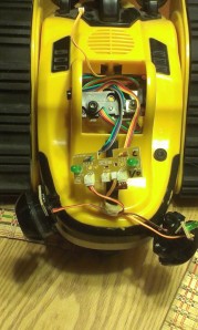


So after taking everything apart and ditching all the extra unwanted body parts, I was left with a tread base, battery compartment, power switch, the original IR sensors, speaker and the main computer control board. That was hacked to allow for arduino control of the H-bridge section. so now came the task of figuring out what was what on the original control board and wiring up the arduino for some basic motor control and maybe some sensor input for obstacle detection.
I had learned a few years back about evosapien.com. They have a section dedicated to schematics of the different wowwee bots, but alas, nothing for the roborover. there was this though.
http://www.evosapien.com/robosapien-hack/nocturnal/RoboReptile/h-bridge.html
http://en.wikiversity.org/wiki/Arduino/WowWeeTriBotArduino
http://myrobothouse.blogspot.com/2011/12/tribot-is-autonomous-robot-from-wowwee.html
The last link was the real helper. I ended up doing something similar to this to take control of the roborover H-bridges with an arduino. It actually works quite well and gives very simple controls in software for moving the robot. Motor 1 and 2 ON/OFF and Motor 1 and 2 Direction. and it was much easier than building a new set of H-bridges for the motors! but more on that later…

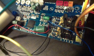


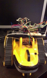
 (I know the photos are bad and you can’t see where to connect to. leave a comment and i can always fill in the details! connections are RED, H-bridges are BLUE)
My handy multimeter told me that there were a few points on the control board that spiked to around +5V when the robot was commanded to move with the original IR remote. More prodding and two points revealed they were the Motor 1/2 ON/OFF control and another set proved to be Motor 1/2 DIRECTION control. a few micro wires lightly soldered into the nearest via’s for those connecting lines (which trace from the H-bridge circuits directly to the on board micro-controller chip) and I had something to plug into the Arduino finally. NOTE: Once you know what micro-controller lines control the H-bridges, you will need to severe those lines from the chip and solder your own wires in to connect to the arduino. BE CAREFUL! I also scavenged the original IR distance sensor from the robots back and mounted it to a servo. It is now mounted out in front and is in use similar to a Sharp IR sensor. It sweeps the front 180 degree field of view and sends signals to the arduino about IR reflections coming back. This in turn controls the treads motor movement (i.e FORWARD,BACKUP and TURN, etc,etc). Arduino connections were Motor 1ON/OFF (pin5), Motor 2ON/OFF (pin6), Motor 1 Direction (pin4), Motor 2 direction (pin3). one day i will reorganize my pin-outs and arduino code to make more sense. but it works for now. 😉


A few tester lines of arduino code and the treads turn on and change direction! and the IR servo sweeps and does its thing! BTW, the Arduino Inventors Kit at Sparkfun (https://www.sparkfun.com/products/11236) is awesome for random projects like this!
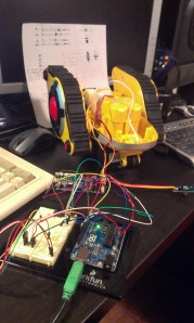
At this point, I was just excited to see if the basic robot worked at all…so i used electrical tape and tried to slam the parts together as fast as robotic-ally(?) possible. It is really shitty. I mean SHITTY! see for yourself…


but IT WORKS! He needs some logic programmed into the arduino now that he has some input and output. Now we are finally getting somewhere. but the tape is awful. Hot glue to the rescue!
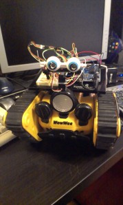
After I drilled out and glued some kinda googly eyes (that I found on the ground of the East Bay mini Maker Fair) on the IR sensor, it was good to go!
There is actually allot more going on with the arduino and breadboard circuit than I have described. I will dive a little deeper.

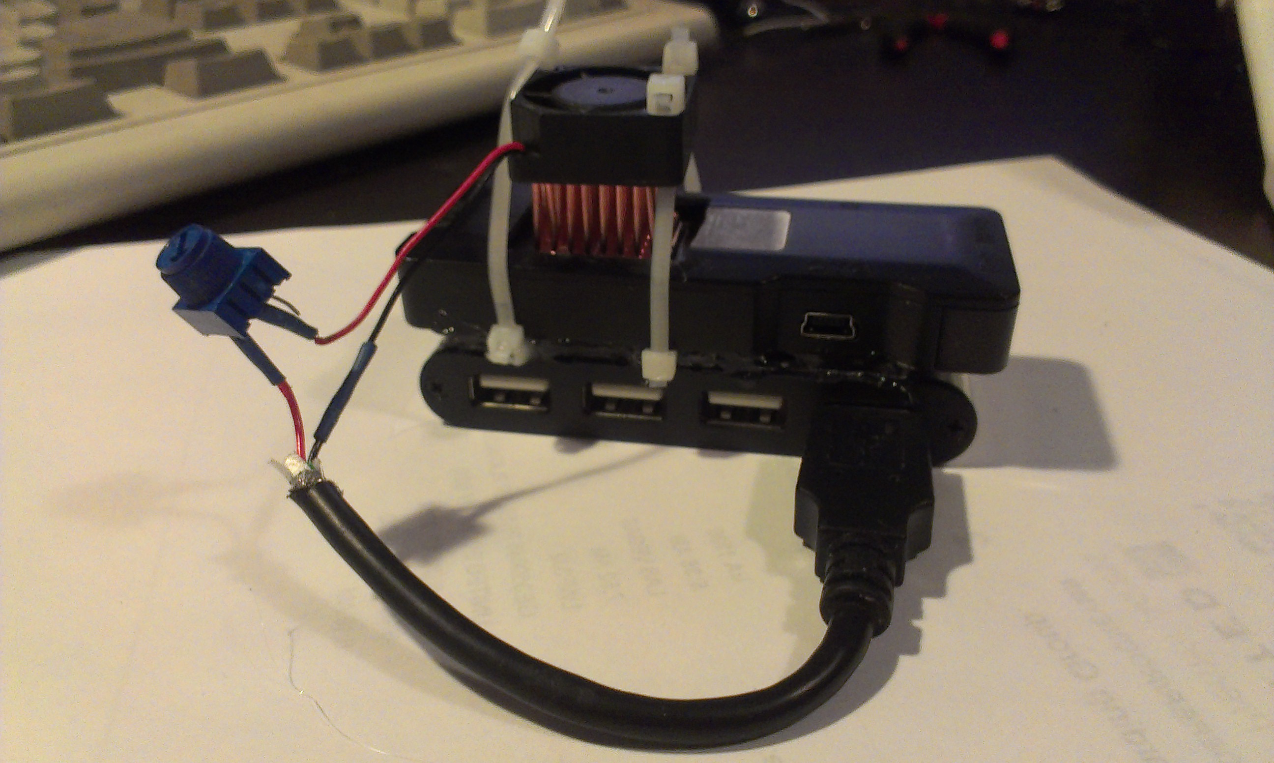
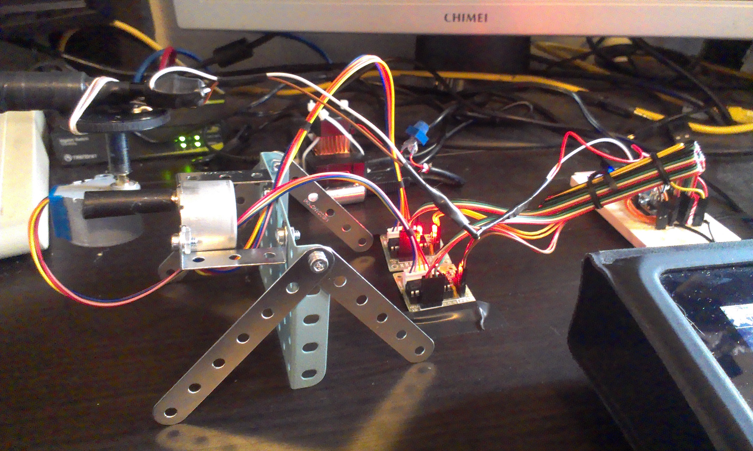
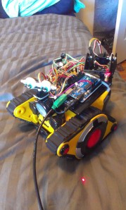
So we have two different controllers running (technically) here. An arduino controlling things, and the original wowwee controller still in there being interfaced for it’s h-bridges. this affords some cool things. For one, we can use the original roborover battery system to power the h-bridges and motors! this includes the original power switch too! all that is required is that wowwee battery negative be connected into arduino ground system (that’s the green wire coming out of the back inside of the tread base in the above photo.) this creates a common connection between both control boards and motor assemblies and is necessary for any function. It might even be possible to power the arduino as well from these batteries but not without replacing the voltage regulator on the arduino first with something more tolerant to a lower input voltage like 6V. I could also cut the power lines to the original microprocessor and other parts on the wowwee board for a little added battery savings. For now, a 9 volt battery powers the arduino and 4 C batteries power the tread motors and h-bridges. the negative of the 6V battery pack on the robot needs to connect to the Arduino ground. not the negative battery lead of the arduino, but on of it’s GND connections on the board itself.
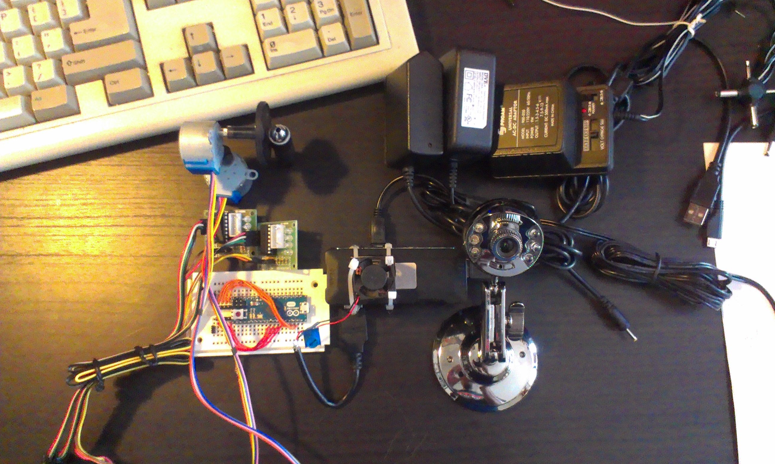
Secondly, there are multiple connections (RED) needed for the IR detection. The emitter LED(BLUE) has power (5V from arduino with 220Ohm resistor) and ground, and the receiver(GREEN) has power(5V from arduino), ground, and signal (to arduino pin9). Some Infrared Detectors signal lines go HI on detection, some go LOW. My arduino code always is my reminder of which one this is. If it’s backwards, just change yer code to reflect when to react to the IR sensor, on signal HI or LOW received. Also notice the IR receiver side has a lens to help focus light coming in and the emitter has a plastic ring shroud on blocking most IR coming from the sides. These pieces proved to be EXTREMELY important for proper obstacle detection. without these parts, the robot just triggers itself constantly from the leaked IR light. The whole IR assembly gets hot glued to the servo seen below and this composes the 180 degree field viewing forward IR detector.

Now to the best part! the original goal of this project was to make a glorified cat toy…so here it is!

so my cats love laser pointers. they never really get bored of it…maybe tired because they are fat cats. so i thought a laser pointer mounted onto a sparkfun 2 axis servo mount would do the trick!
https://www.sparkfun.com/products/10335 -bracket system
https://www.sparkfun.com/products/9065 -small servo (x2)
My arduino sketch already had the servo library loaded up from my IR sensor so that was done. All I needed to do was add the pin definitions of the laser servos to my sketch and some code for some cat approved jerking movements and that was that! A little hot glue and the laser was mounted like a shoulder cannon! I need to create a ton more patterns for the laser to fire in so the cats don’t get too bored with it.


I had to add a few tweaks to the arduino code so that it has a few conditions, like ‘TURN LEFT’, ‘TURN RIGHT’, ‘REVERSE AND TURN’.
and the cats? are they satisfied? here’s one!
(a loose wire and a code typo was prohibiting the robot from turning around in the above video. problem corrected!)
Boom. Kitty approved!
so that was that. I can probably improve the arduino code allot…I already added some code for some bleep sounds(using the original speaker) when he goes in reverse. I was thinking of implementing a timer based system so that more could be done with the arduino during its loop phase. Arduino code can be found linked below. at some point I want to link the arduino to a small android device(mk802)  for opencv integration and maybe some small level of autonomy. now my next step is a solar tracking recharger for the bot..write up coming soon!
![]()
Arduino project –http://www.filedropper.com/glitcharduinocode
just unzip and copy folder to arduino sketchbook folder, then load project.
